Lock-in THD Analyzer (THD+N Measurement)
Warning
This widget has been deprecated. The Lock-in Harmonic Analyzer is now provided as the superior successor.
The Lock-in THD Analyzer is hidden by default. To use it, please add the --experimental flag at startup.
☕ Coffee Break: Filtering out only the "Impurities"
To measure sound distortion (THD), the original clean sound (fundamental wave) gets in the way. It's like trying to find tiny grains of spice in a pot of curry—the curry sauce itself makes it difficult. This tool uses a magical technology called a "Lock-in Amplifier" to pinpoint and "completely erase" only the original sound. What's left over is the "distortion" and "noise". With the original sound gone, microscopic impurities that were previously hidden become clearly visible!
Overview
The Lock-in THD Analyzer is a widget designed to measure "Total Harmonic Distortion + Noise (THD+N)" by using high-precision "lock-in detection" to identify and remove only the fundamental frequency component.
It provides higher fundamental rejection performance than typical FFT analyzers, allowing for accurate evaluation of minute distortion in amplifiers and DACs.
How it Works (Fundamental Rejection)
This widget applies lock-in amplifier technology to calculate THD+N as follows:
- Lock-in Detection: Synchronously detects the input signal with an internally generated sine wave (e.g., 1 kHz) to precisely measure the "amplitude" and "phase" of the fundamental wave.
- Rejection (Notch): Synthesizes a waveform identical to the measured fundamental component and subtracts it from the original signal.
- Residual Component: Measures the amount of the remaining signal (harmonic distortion + noise) after subtraction.
- Calculation: THD+N is calculated as .
Operation
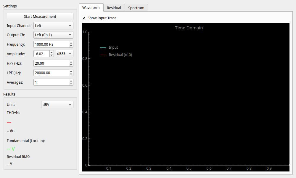
Basic Settings (Settings)
Configure measurement conditions in the left panel.
- Frequency: Measurement frequency. Usually
1000 Hz. - Amplitude: Output level. Match it to the rated input of the device under test.
- Averages: Number of averages to stabilize measurement accuracy.
Filter Settings (HPF / LPF)
This is one of the most important settings in THD+N measurement. It is used to cut noise in unnecessary bands to evaluate pure audio performance.
- HPF (Hz): High-pass filter.
- 20 Hz: Removes DC offset and ultra-low frequency fluctuations. This is the standard setting.
- LPF (Hz): Low-pass filter. Determines the upper limit of the measurement bandwidth.
- 20000 Hz: Standard setting for measuring distortion only within the audible range (below 20 kHz) (e.g., AES17 compliant).
- 80000 Hz or higher: Used for evaluating high-frequency noise in high-resolution equipment.
Reading Results (Result)
- THD+N: Total Harmonic Distortion + Noise. Smaller values indicate better performance.
- -60dB (0.1%): Typical audio equipment.
- -80dB (0.01%): High quality.
- -100dB (0.001%): Professional/High-end grade.
- Fundamental: The voltage of the fundamental wave detected by lock-in.
- Residual RMS: The total voltage of distortion and noise.
Graph Description (Tabs)
- Waveform:
- Cyan: Input waveform.
- Red: Residual Component (Residual) magnified by 10x. A flat line indicates low distortion. Waves indicate harmonic distortion, while jagged patterns indicate dominant noise.
- Residual: Time-series change of the residual component level.
- Spectrum: Frequency analysis of the residual component. The fundamental wave (1 kHz) is cleanly removed, making it easier to see 2nd (2k) and 3rd (3k) harmonics.