Ultrasound Modulator
Overview
The Ultrasound Modulator is a widget that amplitude-modulates (AM) audio signals into the ultrasonic range, making them suitable for playback on ultrasonic reference speakers (typically centered at 40kHz).
When an audible signal is amplitude-modulated onto an ultrasonic carrier wave and emitted, the non-linearity of air causes the sound to self-demodulate in mid-air. This module is used for experiments with such "parametric speakers" that deliver sound only to a highly specific, narrow area, as well as for acoustic measurements in the ultrasonic band.
Key Features:
- Real-time AM Modulation: Modulates a carrier wave (default 40kHz) using the input audio signal.
- Safety Features: Keeps the actual output state, routing, carrier conditions, and calibration status visible, and latches warnings for invalid signals and output above 0 dBFS.
- Flexible Routing: Supports arbitrary selection of input/output channels (L/R/Stereo).
- Pre-distortion: Supports square-root processing to reduce distortion caused by demodulation.
Basic Operation
Starting and Stopping Modulation
Click "Start Modulation" at the top of the screen to start modulation. While output is active, the same control becomes "Stop Modulation", so output can be stopped from either settings tab.
The persistent status area distinguishes stopped, unavailable, ultrasound output, passthrough output, and limited-output states. Input-to-output routing, carrier frequency and mode, and output calibration status remain visible outside the tabs.
[!WARNING] Although ultrasound is inaudible, high-intensity emission can be dangerous to hearing and pets. Always start with a low gain and use appropriate protection. A safety confirmation dialog will appear upon starting.
If the carrier or its sidebands exceed Nyquist at the current sample rate, the status changes to "UNAVAILABLE" and the start control is disabled. Follow the displayed explanation and adjust the sample rate, carrier frequency, or Audio LPF. The default 40 kHz carrier with 8 kHz bandwidth requires a sample rate above 96 kHz.
Parameter Settings
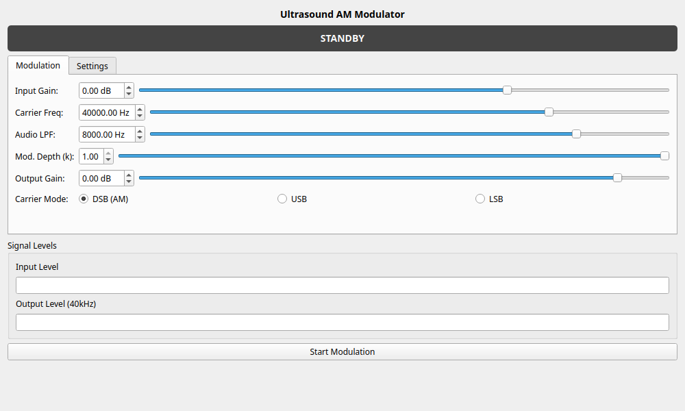
Configure signal processing parameters in the "Modulation" tab.
- Input Gain: Adjusts the gain of the input signal. Use the input level meter to set an appropriate level without clipping.
- Carrier Freq: The frequency of the carrier wave. Set this to match the resonant frequency of your ultrasonic transducer (e.g., 40000 Hz).
- Audio LPF: The cutoff frequency of the Low Pass Filter applied to the audio signal before modulation. Adjust this to prevent sidebands from exceeding the bandwidth limits.
- Mod. Depth (k): The modulation depth (0.0 to 1.0). 1.0 indicates 100% modulation.
- Output Gain: The output gain after modulation. Operate with caution for safety.
- Carrier Mode: Select the modulation mode.
- DSB (AM): Standard Amplitude Modulation (Double Sideband).
- USB: Upper Sideband modulation. Used for bandwidth saving or specific experimental purposes.
- LSB: Lower Sideband modulation.
Routing and Settings
Configure input/output routing in the "Settings" tab.
Input/Output Channel
Select the input source and output destination.
- L / R: Processes as mono.
- Stereo: Processes as stereo signals (carrier phase is identical for both).
Advanced Options
-
Enable √ Pre-distortion: Applies square-root processing () to the signal beforehand to correct distortion that occurs during amplitude demodulation. This is useful for reducing distortion during self-demodulation in parametric speakers.
-
Bypass Modulation: Outputs the input signal directly without modulation (gain is still applied). Use this for checking settings or as a pass-through output.
Signal Meters
The "Output Monitor" on the right shows input and output RMS levels in dBFS. Use it to verify that a signal is present and that the output is not saturating.
- Input RMS: The audio level after input gain and before modulation.
- Output RMS: The signal level after digital output limiting.
If the output exceeds 0 dBFS, it is limited to digital full scale and the warning is latched. Lower the gain, then use "Clear Peak" to acknowledge the warning. When output is uncalibrated, these are relative digital levels and do not represent the transducer's physical sound pressure or voltage.